[Hey, peeps! I make roleplaying games, science fiction and Sword & Sorcery art, and other cool stuff! Back me up so I can make more!]
I’ve been building synthesizers for about a year now. My first, BRIGAND, got lost on the way back from Richmond, VA, where it was part of a recording for WRIR, Richmond Independent Radio. That recording is now on my Soundcloud as the self-titled EP by Def Sensor.
I put off rebuilding it out of frustration more than anything else. But then I started to think about how I could use Control Voltage/Gate (“CV/Gate”) to integrate it with other noiz machines. It took me several weeks, but finally, BRIGAND is reborn as SCION! (Sorry it’s so quiet! It didn’t used to be? Not sure what happened! There will be more later, though!)
SCION started off as a breadboard mockup where one potentiometer was mashed together with an optocoupler to give input from another oscillator, keyboard, or…who knows! It could be anything that generates 0-5 volts!
I also had found that I really liked the absolute low end of the frequency slider, even going so far as to trigger the grains at arbitrary, very low rates, like once a minute or so, so I wanted a trigger key that would give me the ability to make it pscheeeooowwwzzzzz whenever I hit it.
Once I had the board working reliably, I started reworking the code to allow me those very low repetition frequencies, including single, non-repeating pulses. Fortunately, The firmware, called Auduino, is a granular synthesizer designed to run on Arduino boards. It’s almost disappeared from the Internet, so I took my rewrite and started the Auduino2 GitHub project. Please feel free to download it and tell everyone what you made with it! You should be able to adapt it to make all sorts of weird sounds!
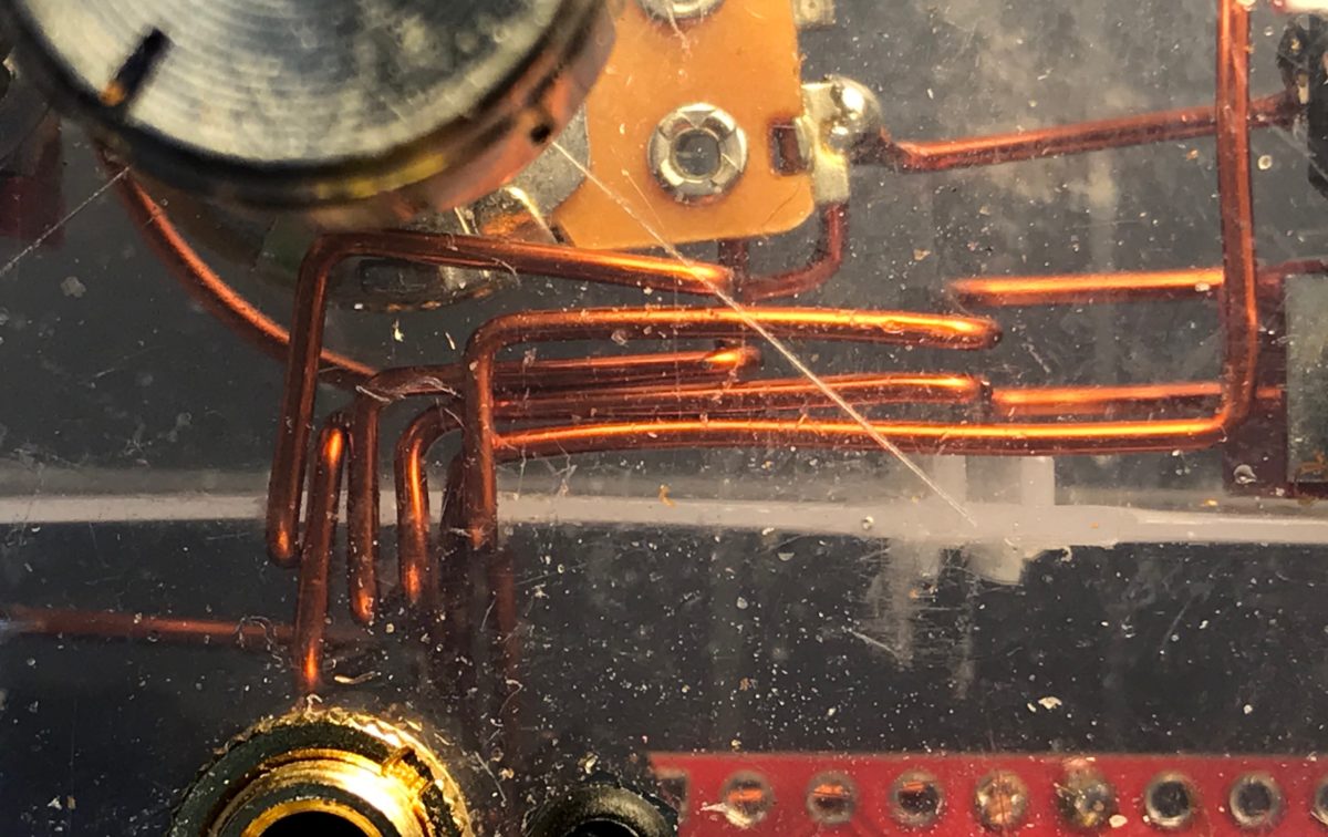
Once I had the development board programmed and everything seemed to be working, it was time for a case and solder. And, since the case I wanted to use was transparent like BRIGAND was transparent, I wanted wire that looked good. BRIGAND had used bare bus wire for the power rail, and I loved the way it looked, but bus wire is uninsulated. If I was to run all my wire like that, I’d need to use enamel wire, then remove the enamel insulation wherever I needed it to make contact.


I also had to build a bunch of optocouplers, also known as vactrols (a genericized brand name for them). The way the work is that, effectively one side is a light and the other side is a photoresistor. As the light gets brighter, the resistance drops in the photoresistor. They’re fun to stick out in the air, but that makes them subject to ambient conditions. I opted to mostly isolate them, though I left the ends open to allow for ambient weirdness.
What that allows you to do is send a signal — in this case, a signal of any sort, as long as it’s between 0V and 5V — directly to the control potentiometers. It’s a really simple process that lets you build an analog communication network between devices without worrying about uneven ground levels or whatever.
Here’s how I built them:
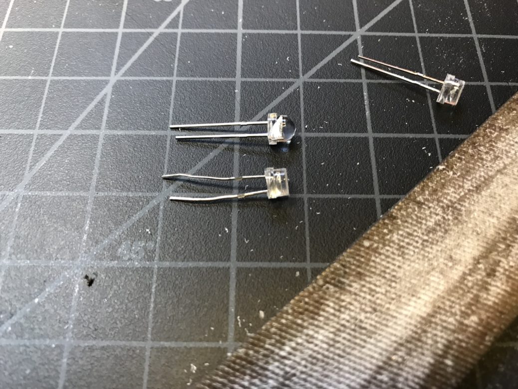
The lens on LEDs is meant to spread out the light. But I want it to go straight into the photoresistor, so I filed it flat. 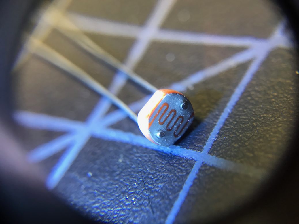
The two leads on the photoresistor extend above the face. I filed them down so they could mate better. 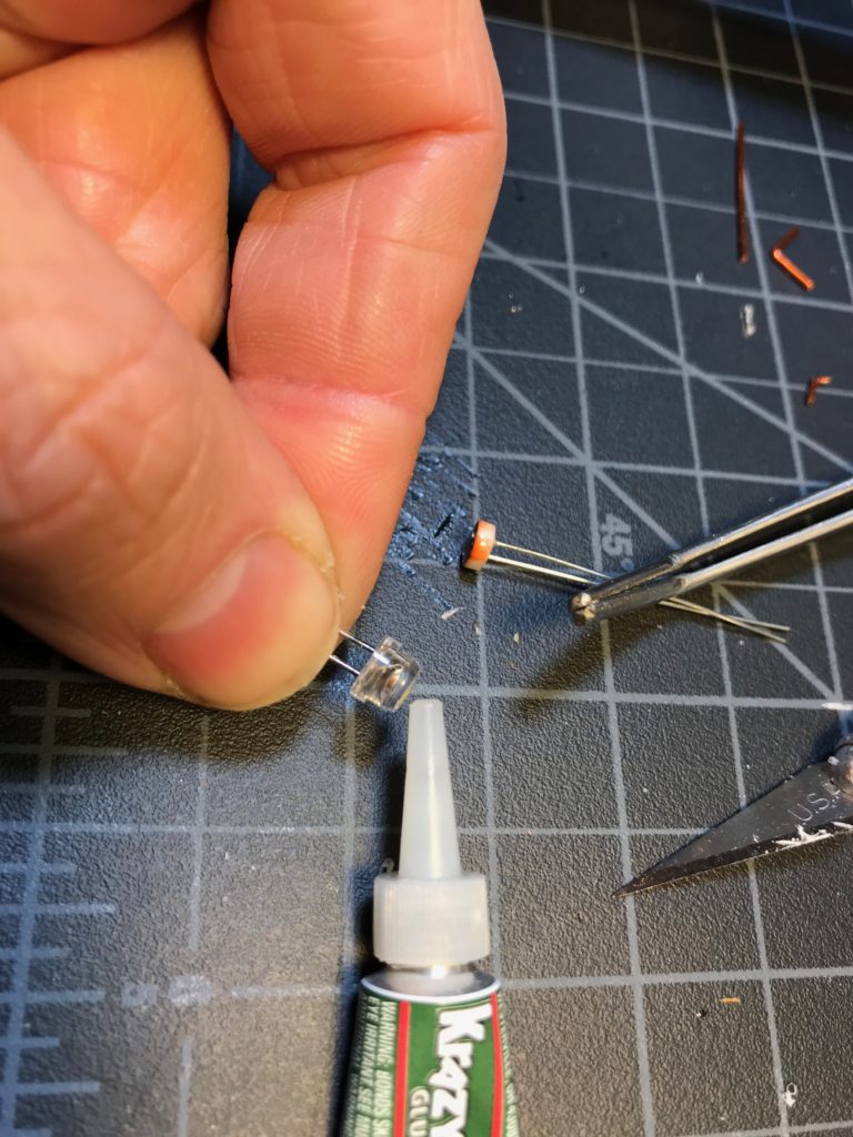
Superglue the LED 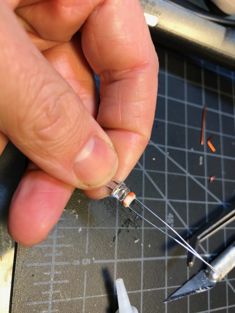
Glue the LED to the photoresistor 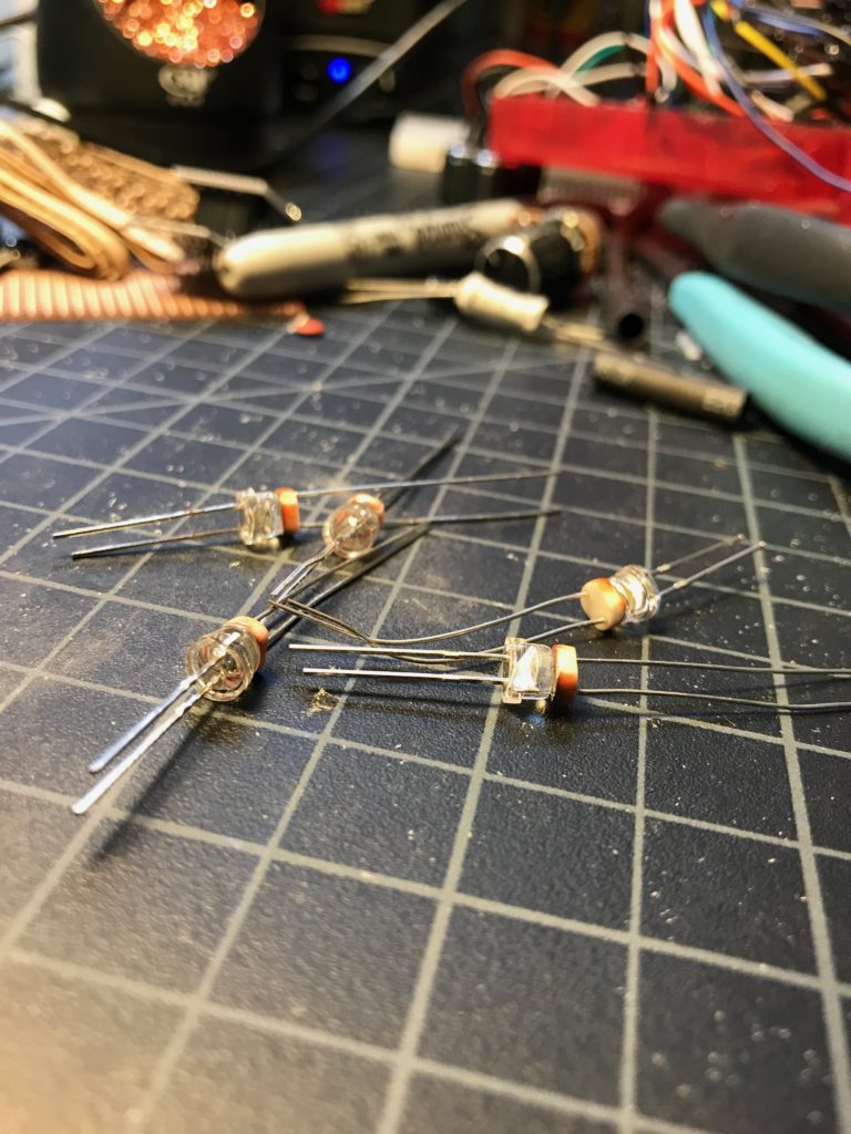
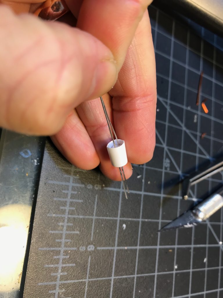
I’m using two layers of heat shrink. The inner one, the white one, is to prevent loss of light. 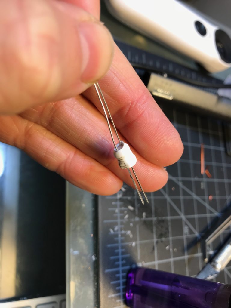
Shrink it! 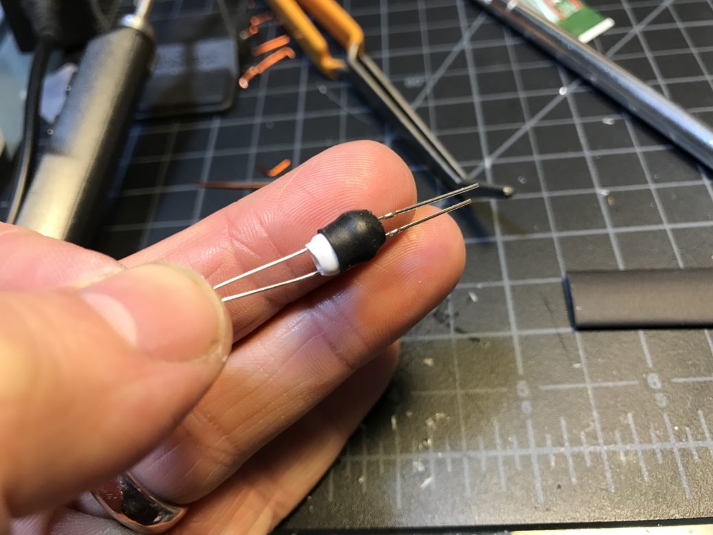
This is supposed to block out external light. I left part of the white sticking out so I could be sure which end was which. The output side is white, but I’d recommend covering the output and leaving the markings on the input.
Oh, about the transparent case. It’s a parts box. I’m not sure what came in it. Maybe some potentiometers. It’s a little softer than I’d like, it turns out. It makes the button a little unresponsive and plugging and unplugging the jacks is a little harder to time well.

Measure and score 
I’m using the shapes in the box as a guide. 
Rough layout of the controls and jacks. 
Paper punch to make room for the wires. 
Then, pilot holes! 
…and hole holes! 
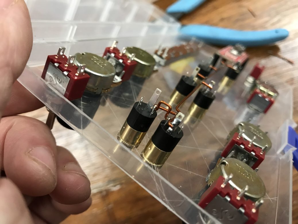
These toggles connect the optocouplers to either ground-signal or power-signal, determining which way they control. 
Potentiometers in place 
Switches and control pots. Grain1 on the left, grain2 on the right, frequency on top and decay on the bottom. 
There are some controls I hadn’t thought out all the way, like a way to turn the trigger (the LED button in the lower right) on or off vs. using the Gate signal.
Next up, I needed to get down to wiring.
The Gate signal can come from any input, so they’re all connected. 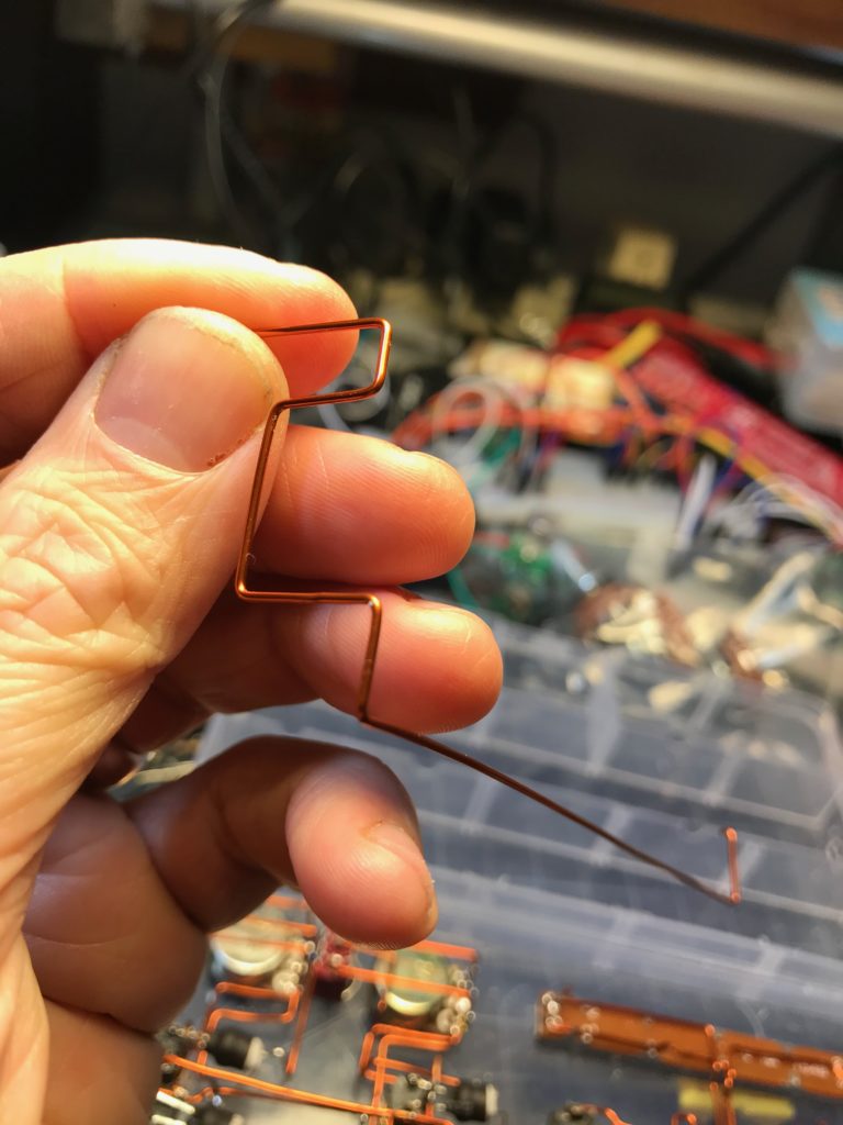
Every wire is bent to its unique shape and its insulation scraped off. 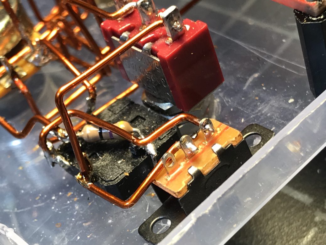
Switch for manual/auto trigger. 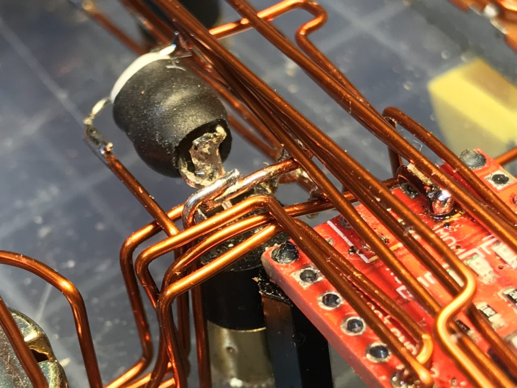
A confusing little bus for audio output and Gate signal. I made several mistakes in this confusing spot. 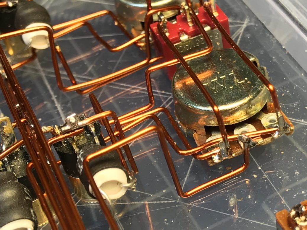
The grain1 decay optocoupler, signal inverter switch, and potentiometer. 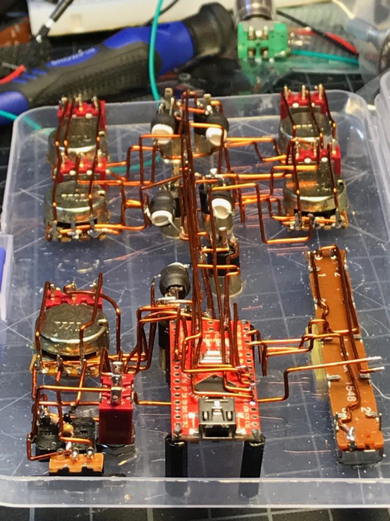
All the wires, sans audio jack. 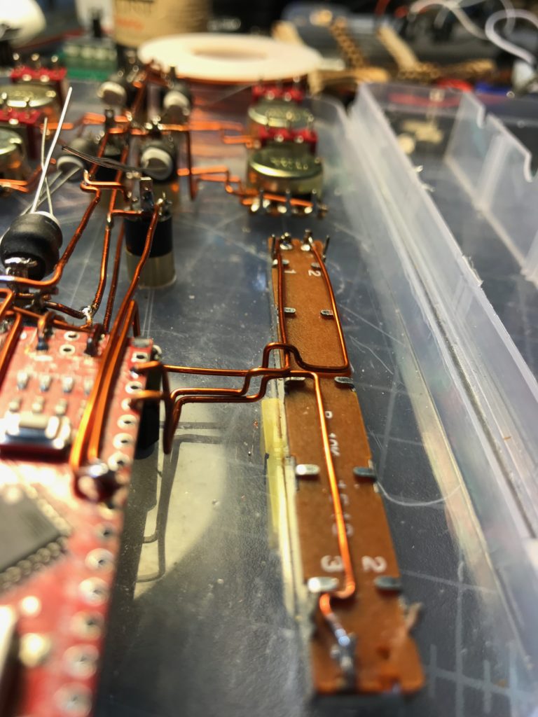
This wire is so fun to work with.
There are a couple of features I want to add. One “feature” is that one of the potentiometers doesn’t seem to work, and I’ll have to somehow perform surgery to replace it.
Another is that I think I need to install a small amplifier in it. The quiet of the video comes from a terrible solution (miccing a speaker!) to an awkward problem (plugging into a mixer seemed to draw too much current).
I also want to install a three-position switch so I can move from the drumlike repetition frequency can get up into audio frequencies. This kind of synthesis is great at making voice-like sounds (it’s the root of sampling technology) when the repetition frequency is higher.
There are more such noizmachines coming! The purpose of that control voltage is to get them all talking with each other. And it really feels like space exploration as you wander around complexly-interacting waveforms.

One thought on “Build a SCION”